Computer Aided Design and Manufacturing (CAD – CAM).

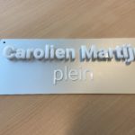
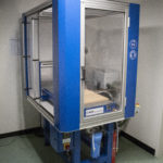
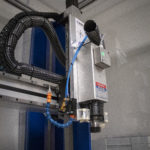
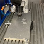
Recently the Instrumentation and Engineering Department acquired a CNC portal milling machine.  This enables the computer aided manufacturing of 3D objects in plastic, wood or metal.  This Rapid Prototyping is done within the CAD-CAM process.

Process steps

In the CAD process, a virtual model is created by drawing it in a 3D software package like Blender. This model is based on the client’s specifications and can be used to get client feedback to see if the final product meets the client’s requirements.

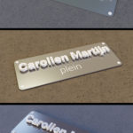
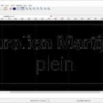
Blender’s output files are used in the next step. In this step a technical drawing is made, based on the virtual model. The software used in this step is AutoCAD or Solidworks. This technical drawing is the base for the CAM process.

After designing an object in the CAD process, the object must be translated into something that the prototyping device can handle. This translation is done in the CAM process. In the CAM process, the model is read and prepared to be converted into a physical product by, for example, a 3D printer or CNC mill.  Software used in this step is VCarve Pro, it generates the G-Code which controls the CNC machine.